Introduction
In a previous post, I outlined the design requirements for the inverted pendulum (IP) problem and ran Matlab simulations to demonstrate how the IP controller can be tuned to create a stable closed-loop system. In this post, I will be translating the design objectives into system function objections as they pertain to the electrical system of the IP robot. The electrical system must accomplish the following tasks:
- Measure pendulum angle and angular velocity
- Provide control action
- Measure cart position and cart velocity
- Process data and execute instructions
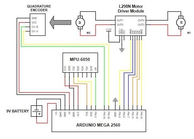
The total electrical diagram to address the design criteria is shown in Figure 1. In the rest of the post, the specific components from the circuit will be introduced as well as the functions the components provide within the circuit and the design choices that led to that specific component being chosen.
MPU-6050
One of the fundamental measurements that must be performed in order to implement the full-state feedback controller described in the Matlab simulation post is the measurement of the angle of the pendulum. The component which fulfills task 1. of the electrical functions a.k.a. measures the angle of the pendulum, must be accurate, fast, and compact in order to be deployed on the IP robot. Luckily, there are a number of prefabricated modules cheaply available. The MPU-6050 is easily available at many online stores, such as Amazon, is clearly compact, as shownm in Figure 2, and it is quite fast. The MPU-6050 houses a 3-dimensional gyroscope as well as a 3-dimensional accelerometer which is enough to construct accurate positioning information about the pendulum angle when a Kalman or complementary filter is used on the data. However, it is not necessary to even write code for this module to unpack the data since the MPU-6050 houses a digital-motion-processor (DMP) which outputs accurate position information directly. When the data is ready, the "INT" pin in Figure 2 changes, and the micro-controller can then read the data out. Note that the DMP only outputs angle data and not angular velocity data. On the micro-controller, this means a first order backward differentiation must be performed on the measured angle data in order to obtain angular velocity data as well.
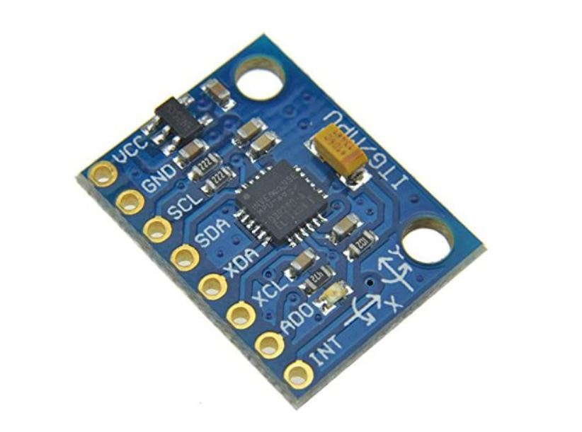
In terms of the electrical requirements of the MPU-6050, the "Vcc" pin takes 3.3 V which can be provided by the micro-controller, the "SCL" and "SDA" pins must be connected to "SCL" and "SDA" pins on the micro-controller to establish I2C communication, and the "INT" pin should be connected to an interrupt pin.
Brushed DC Gearmotors and DC Motor Control
The second criteria the electrical system must fulfill is the ability to provide sufficient control action to correct disturbances to the IP. In the case of an IP robot, a motor of some sort is the clear option but depending on the specific system, vastly different control mechanisms can be employed to provide control action. For example, SpaceX is renowned for its upright-landing booster rockets. That system is clearly an IP and the control action to keep the rocket upright is provided by changing the direction the exhaust leaves the rocket so as to counteract movement at the nose of the rocket. Other IP projects balance the pendulum using the printer-head track from a dilapidated printer. In short, there really is no right answer when it comes to selecting the component which provides the control action so long as it satisfies the design criteria laid out for the project. Returning to our IP robot, there is a plethora of types of motors available to choose from; however, brushed DC motors have the advantage of usually being cheaper and more simple to operate.
We can further refine the selection of brushed DC motors we have to choose from by considering how the motor will be operated to control the IP. As stated in the Matlab simulation post, the average cart velocity will be zero. We also know that if the IP is balancing well, the wheels should barely be turning and only turning fast to provide correcting action after the IP has been bumped or disturbed. Therefore, motors which can turn slowly well will perform the best. This naturally leads to the consideration of a brushed DC gearmotor as a suitable candidate for the IP robot.
The American manufacturer Pololu offers a range of brushed DC gearmotors available at various gear ratios and input voltages as shown in Figure 3. For this project, the 6V low-power 47:1 gear-ratio gearmotors were chosen. This gear ratio would offer a balance of suitable performance at both slow and fast rotation speeds. A voltage level of 6V was chosen for reasons related to best practices for controlling motors at slow speeds. DC motors suffer from substantial friction between the carbon brushes carrying current and the rotor. As such when a voltage is applied to the motor terminals, the voltage must build up to such a level that the electromotive force can overcome the friction force from the brushes. Using a voltage of 12 V in this case helps the motor receive the voltage necessary to overcome the internal friction faster as well as jerks the rotor into motion. Combined, this helps the motor to turn at lower speeds than if 6V was used. The only thing to watch out for is that the duty cycle of the pwm signal sent to the motors is halved such that the maximum allowable duty cycle is 50%. This helps prevent shortening the life of the motor due to winding overheating.
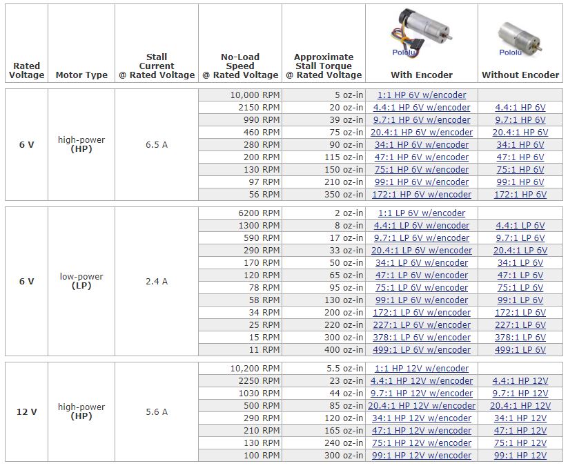
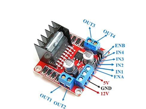
With the gearmotors selected, the motor control unit can be discussed. As you can probably guess from the data provided in Figure 3, the current and voltage requirements for these motors easily exceeds the capabilities of almost all micro-controllers. Therefore, the power from the motors will have to come from an external source. In this IP robot, a 12V/5A supply connected directly to mains voltage was used since it was readily available instead of a battery pack. The 12 V supply was connected to an L298N module which serves as a simple interface for the microcontroller to use to control the operation of the motors. An image of the L298N module is shown in Figure 4.
The L298N allows the control of two DC motors at a time. One set of motor terminals is connected to OUT1 and OUT2 and the other set of motor terminals is connected to OUT3 and OUT4. ENA is for OUT1/2 and ENB is for OUT3/4. The enable pins must be set high to send power to the respective motor. Lastly IN1/2 controls the polarity of the voltage applied to OUT1/2. Setting IN1/2 to the same state (HIGH or LOW) causes braking action on the motor whereas IN1 set to HIGH and IN2 set to LOW, or vice versa, causes forward or reverse motor action. The analogous relationship exists for IN3/4 and OUT3/4.
Regarding the electrical requirements for the L298N board, we already discussed that 12V is connected to the 12V pin on the board. Since the motor voltage is not greater than 12 V, no 5 V supply is required to be plugged in. The L298N uses an onboard regulator to step-down the 12 V to the 5 V required for the IC logic. The last thing to note is that the board has a maximum output current of 2.5 A, however, the motors are unlikely to require this much current during their operation so this limit is suitable.
Quadrature Encoder
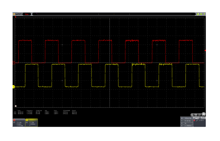
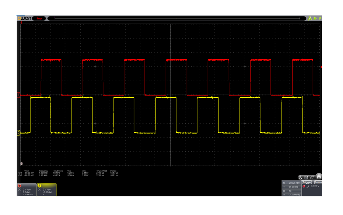
As mentioned earlier in the post, the angle of the pendulum must be measured as well as the position of the cart. Quadrature encoders satisfy the latter criterion. Quadrature encoders attach to the shaft of a motor and can use light or magnets to trigger an impulse on a sensor as the motor shaft rotates. Based on the number of impulses expected per rotation of the motor shaft, counting the number of impulses can provide information about the position of the motor shaft. The quadrature encoders used in this project came preassembled on the gearmotors from Pololu. As mentioned in the datasheet, two hall effect sensors are used to measure the magnetic fields from a small disk embedded with magnets which rotates about the motor shaft. As magnets pass the hall effect sensors, rising and falling edges are produced on the channel A and B pins which can be counted to provide information about how far the wheel has rotated as well as how fast the wheel is rotating.
The two channels are positioned 90 degrees out of phase to allow for motor direction to be measured as well. This is can be seen in Figures 5 and 6. By comparing the sequence of rising and falling edges coming from channel A and channel B, that is to look for which channel sends a rising edge first, we can see that channel A is leading channel B, indicating forward motion. The assignment of forward motion depends on how the L298N and motors are connected so it is essentially arbitrary. However, continuing with this convention for direction assignment, in Figure 6, we can see that channel B is leading channel A so the rotation direction must be backwards now.
In terms of actually measuring the distance the cart has travelled and the cart velocity, the datasheet says there is 48 counts per revolution of the motor shaft when both edges of both channels are counted. If the gear ratio for the gearmotors is 46.85:1, as described by the manufacturer, then the counts per revolution of the gearbox output shaft would be 48 x 46.85 = 2248.86 counts. Since there is 360 degrees per rotation, we can then compute the angular displacement of the wheel for each time a count is measured. Dividing 360 degrees/rotation by 2248.86 counts/rotation, we have 0.16008 degrees/count. Interrupts are used to count the edges from channels A and B, so that no counts are missed, and a timestamp can be taken every time an interrupt is triggered to obtain the angular velocity of the IP robot wheel. Finally a simple arc angle calculation can be completed based on the radius of the wheel and the wheel angular position information to determine cart position and velocity.
The last thing to discuss about quadrature encoders before moving on is the electrical requirements. The Vcc pin requires a voltage greater than 3.5 V so a 5 V pin on the microcontroller should used. Mentioned in the last paragraph as well, two external interrupt pins must be available on the micro-controller to count the edges from the hall effect sensors.
Arduino Mega 2560
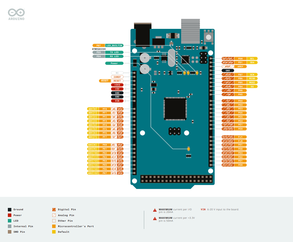
As can be seen from Figure 1, all of the components in the IP robot are connected to the micro-controller. The micro-controller fulfills the final function of the electrical system for the IP robot by processing data and executing the closed-loop controller instructions. The micro-controller reads in data from the MPU-6050 and the quadrature encoders to ascertain the position and velocity states of the pendulum and cart. Using this data as input to the full-state feedback model, a command is then sent to the motors to apply a particular force for the duration of the current time interval. The selection process for the micro-controller to be used on the IP robot is somewhat simpler than the process for selecting the motors. In short, the micro-controller should have hardware PWM capabilities, have a sufficient number of external interrupts, have reasonably high processing speeds, and be easy to power.
In my lab, I had a Raspberry Pi (RPi), an Arduino Uno, and an Arduino Mega 2560. The requirement for hardware PWM ruled out the RPi as a candidate for this micro-controller implementation. When a micro-controller is operating software-based PWM control, as would be done on the RPi, whenever the RPi executed instructions that were not related to running the PWM, the PWM signal to the motors would go dead and the motors would begin coasting. Since our Matlab model assumes that PWM control is always available to control the motors, and this motor cutout would occur every time we ran through the control loop, our Matlab model would no longer describe our physical control loop. In summary, the IP robot may no longer be a stable-closed loop system under these conditions. This left the Uno and the Mega as the last two options. The total number of interrupts required by the hardware described in this post totals three. One for the MPU-6050 and two for the quadrature encoder. Since the Uno only has two interrupts, it was immediately ruled out leaving only the Arduino Mega 2560, which has six external interrupts, as the sole candidate. Last two criteria for processor speed and simple power setup are also easily achieved. The Mega has a processor speed of 16 MHz and can be powered for hours on only a 9V battery.
