Introduction
In the third installment of my Self-Balancing Inverted Pendulum series, I will be presenting the mechanical design portion of this project. The design objectives will be discussed as well as the fabrication process and limitations. This will be followed up by pictures of the mechanical drawings and assembly produced in Autodesk Inventor and presentation of the physical measurements of the IP implementation. These measurements will be used in the Matlab model, from the first post of this series, to obtain the tailored full state feedback controller for this system. Without further adieu, lets jump in!
Design Objectives and Fabrication Process
It may be somewhat strange to group these two topics together, however, for this project, and my limited home fabrication capabilities, it was necessary. At my lab at home, I have a 3D printer so naturally I wanted to design a body for the inverted pendulum (IP) that could be 3D printed rather than try to fabricate some complex assembly from sheet metal or something to that effect.
A benefit of the 3D printer too is that it can print a complex structure accurately all in one shot, assuming the CAD model is set up correctly. There are some limitations, however. The size of the bed the printer deposits material on has a finite size of 210 mm x 210 mm and in practice you usually stay a couple cm away from the bed edges. Our functional bed area is more like 180 mm x 180 mm. Additionally, due to the fact that the printer deposits material layer-by-layer by increasing the printer head height after each layer is completed, structure overhangs greater than 75 degrees require support material to be printed in order to support the structure. The added support material increases post-processing time for the part and can ruin the finish of a print in certain sections. Ideally, we want the amount of support material to be at a minimum.
Considering these limitations, we can begin defining the design objectives for the IP structure:
- Securely house all system components i.e. Arduino Mega, MPU-6050, motors, etc.
- Minimize support material required
- Maximize center of mass height
The last objective comes out of the dynamics of the system. If the center of mass is higher, then the cart will not need to apply as large of a torque to provide correcting action to the system. Therefore, it should be easier to control the system without requiring more powerful motors.
The last thing to touch on is the size of the pendulum. The modelling equations tell us a larger pendulum is easier to control, however, for a given angle of pendulum deviation the motors will also need to be faster in order to cover enough distance to correct the pendulum disturbance. Smaller pendulums can then handle larger deviations of the pendulum with the same motors which also happens to be more entertaining. Therefore, we have bounded the pendulum size i.e. the pendulum needs to be just large enough to house all the system components and no more.
Mechanical Drawings
In the following section, drawings of the IP structure will be presented along with any relevant discussion pertaining to the drawings. The IP structure was designed to fulfill the listed objectives from the previous section. Note that while the Matlab model assumes that the pendulum and cart are separate structures coupled through a pivot point, the pendulum-cart system in this project are rigidly connected. The pivot point of the pendulum and the axle of the cart are coincident.
An overview of the pendulum housing is provided in Figure 1. There are three standoffs (or levels) on the structure. The topmost standoff, beneath what could be called the roof, holds the L298N motor diver and the 9 V battery. The second highest standoff holds the Ardunio Mega 2560 and includes cutouts on the wall so that the USB and power supply ports can be accessed while the IP is assembled. The third standoff is an open space to allow pins from the MPU-6050 to hang down. The MPU-6050 is bolted to some perf-board and then the perf-board is mounted to the holes seen on the standoff. At the bottom of the pendulum is the connection point to the cart. The teeth on the connection limit movement in the x and y directions and the holes on either side allow a bolt to threaded through connecting the cart and pendulum and to limit z movement.
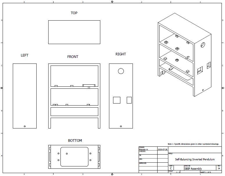
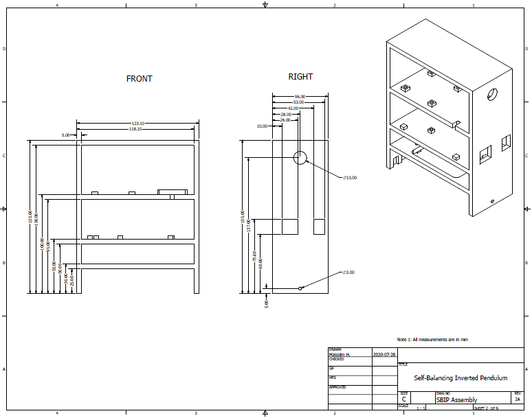
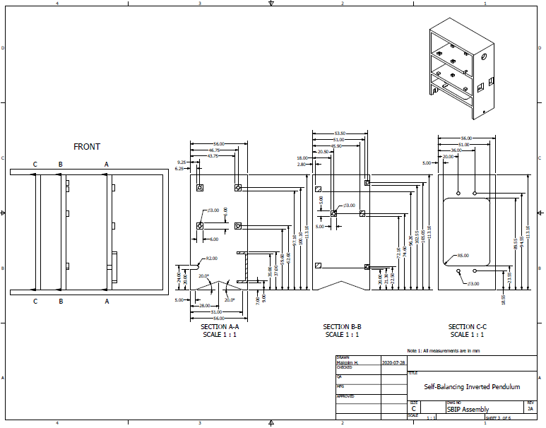
External dimensions for the pendulum structure are shown in Figure 2 as well as the height of the standoffs. Figure 3 goes into more detail of the standoffs by dimensioning the connection points to secure each of the system components to the pendulum structure. The dimensions for the connection points were determined using the datasheet for the component, when available, or by direct measurement, when unavailable.
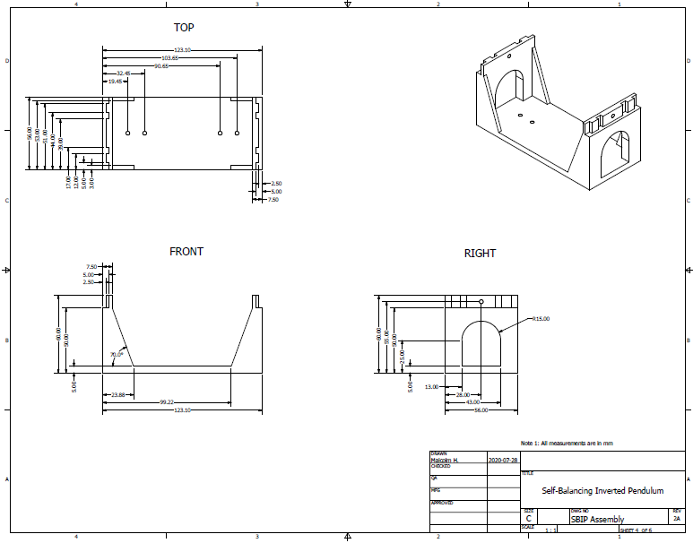
Now we can move onto describing the structure for the cart. The cart will securely hold the gearmotors, and wheels will be attached to the gearmotor output shaft to provide locomotive action for the IP control system. Figure 4 shows the dimensioning of the cart. At the top of the cart is the inverse of the connection seen in Figure 1 which allows the cart and pendulum structures to be coupled together. The arch cutaways were sized to fit the diameter of the gearmotor body as well as some additional height added by the mounting brackets bought from Pololu. The mounting holes on the base of the cart were positioned so that the gearmotors mounted on the mounting brackets could be fit snuggly in the cart structure.
The diagram for the IP wheels is shown in Figure 5. The larger center hole is there to provide space for the gearmotor axle to protrude through and the four smaller holes are there to facilitate mounting the wheel to the mounting hub for the gearmotor axle. A shallow channel is present along the circumference of the wheels to improve the coefficient of friction of the wheels. 3D-printed plastic on a wood surface has very poor traction so rubber bands were fitted into the channel so that the wheels would not slip or spin when the motors begin rotating.

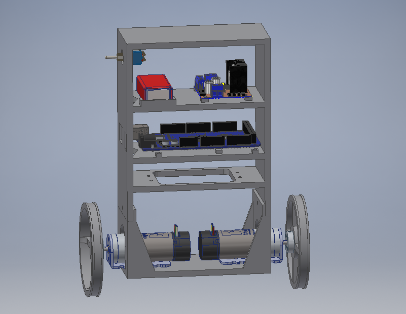
Finally, Figure 6 shows the drawing of the IP assembly including models of the Arduino Mega 2560, L298N, 9V battery, gearmotors, mounting brackets, and mounting hubs for the wheels. The wired connections are left out of the diagram as well as the MPU-6050 and its mounting board. Figure 7 shows the Autodesk Inventor model used to create the drawings in Figure 6.

Implementation and Mechanical Data
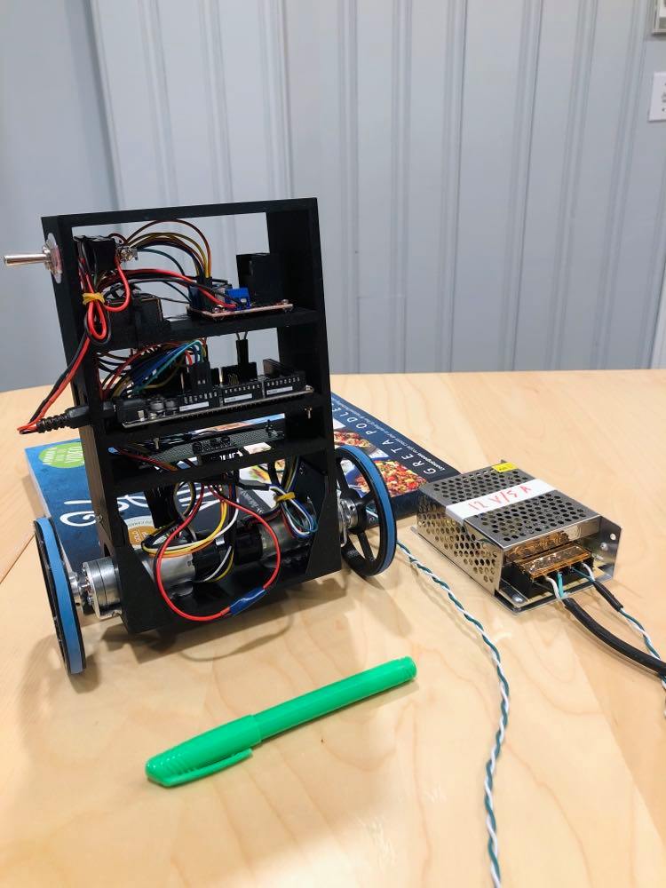
The models documented by Figures 1 through to 7 were used to create 3D printer code using standard 3D printer slicer software. The fabrication process consisted of four separate prints: one for each of the pendulum, cart, and the two wheels. Once completed, the system components were fastened to the 3D printed parts using M2 bolts, washers, and nuts. The wired connections were also added and the pendulum was fastened to the cart. The last part of assembly involved mounting the wheels to the mounting hubs and then mounting the mounting hubs to the gearmotor output shaft. The fully assembled IP is shown in Figure 8 along with the power supply used to power the motors.
With the IP constructed, our attention can be turned back to the full state feedback controller. Several physical parameters are required in order to create an accurate Matlab model for this system: the mass of the cart, the mass of the pendulum, the length to the pendulum's center of mass, and the pendulum's moment of inertia. The length to the pendulum center of mass was found by balancing the IP on its side on a ruler. This point was then measured from the axle of the gearmotors and found to be equal to 0.123 m. After uncoupling the pendulum from the cart, the parts were weighed separately. The cart was found to have a mass of 0.316 kg and the pendulum was found to have a mass of 0.334 kg.
Since for this robot, the pendulum cannot be approximated as a long thin rod, an alternative moment of inertia calculation must be performed. Wikipedia provides a list of formulas for moments of inertia including one for a rectangular plate with the axis of rotation at the end of the plate as shown in Figure 9. The gearmotor axle from the IP can be aligned with the axis of rotation shown in Figure 9 to compute the moment of inertia for the IP.

From Figure 2 we see that the depth of the pendulum (56 mm) aligns with the dimension w shown in Figure 9. The dimension h is measured from the axle of the gearmotors to the top of the pendulum and found to be 0.184 m. Using the formula from Figure 9 as well as the mass of the pendulum, the moment of inertia for the pendulum is calculated to be 0.00386 kg m^2.
In the next post, the Matlab script from the first post in this series will be used to generate the weighting factors needed to create a closed-loop system for the IP. Then the controller will be uploaded to the IP robot, the robot will be tested, and this series will conclude!